Our range of Resilient Couplings give you a combination of advantages of high power rating of a gear coupling and flexibility of elastomer coupling. They are easy to install and simple to maintain. The flexible grids are quickly replaceable without disturbing the connected equipment.
Resilient Couplings are available in broad range of sizes covering from 0.45 kW to 1307 kW per 100 rpm and bores upto 267mm.
CONSTRUCTION : A High torque Resilient Coupling basically comprises a grid spring which connects two hubs – one on the driving and the other on the driven shafts – through axially cut grooves around the peripheries of the two hubs. The spring, which is of special design compatible to the required characteristics of the system, form a series of resilient bridges along the grooves. The grooves are flared to allow the grid members long flexible spans under normal loads as well as better support by the sides of the grooves under over load conditions.
The stiffness of the spring and thus the coupling depends on the length of each flexible span not in the contact with the grooves. Subsequently, the contact length changes with every variation in torque, resulting in change in the stiffness of the coupling at every instant during a vibration cycle. Consequently this produces a powerful detuning action resulting in continuous alteration of the torsional vibration frequency and prevention of a build up of resonance in the system.
The principle of design adopted in Resilient Coupling, makes it capable to accommodate considerable axial, parallel and angular misalignment between a driving machine and a driven machine. Simultaneously, it can absorb considerable overloads due to high torque with consequent reduction in wear and tear on plants and machinery. With the use of resilient couplings, break-down and down time in any manufacturing unit, will be minimum.
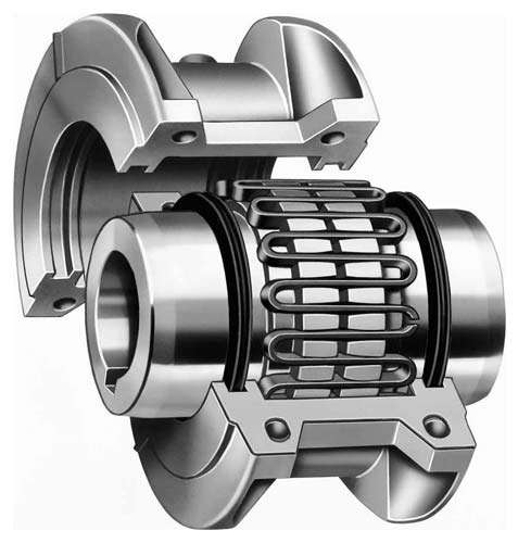
Resilient Coupling
BENEFITS :
1) Protection against shaft misalignment :
Parallel: The movement of the grid in the grooves accommodates parallel misalignment and still permits full functioning of the grid-groove action in damping out shock and vibration.
Angular: Under angular misalignment, the grid-groove design permits a rocking and sliding action of the grid and hubs without any loss of power through the resilient grid.
Axial: End float for both driving and driven members is permitted because the grid slides freely in the grooves
2) Protection against Shock loads, Vibration & Thrust loads:
Light Load: The grid bears near the outer edges of the hub teeth. The long span between the points of contract remains free to flex under load variations.
Normal Load: As the load increases, the distance between the contact point & on the hub teeth is shortened, but a free span still remains to cushion shock loads.
Shock Load: The coupling is flexible within its rated capacity. Under extreme over-loads, the grid bears fully on the hub teeth and transmits full load directly.